Showing posts with label impedance. Show all posts

Saturday, February 1, 2025

TI-84 Plus CE and DM42: RLC Circuits

TI-84 Plus CE and DM42: RLC Circuits


The program RLC calculates:


(1) The total impedance across the entire circuit

(2) The phase angle, sometimes known as a power factor angle

(3) The total supply current


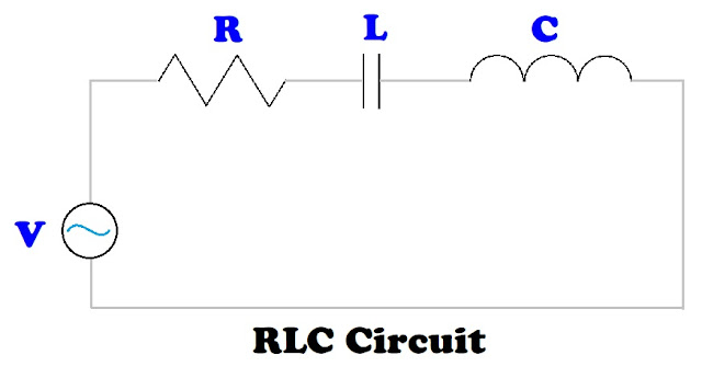
An RLC circuit is a circuit that connects one power supply to a resistor, an inductor, and a capacitor. The resistor, inductor, and capacitor can be connected in one of two ways: series or parallel. To calculate the total impedance (Z) and phase angle (θ), the rectangular to polar conversion function can be utilized.


In a general rectangular to polar conversion, (x, y) to (r, θ):

r = √(x^2 + y^2)

θ = arctan(y / x)


Formulas


Angular Frequency: ω = 2 * π * F


F = frequency in Hz

V = supply voltage (volts)

R = resistor in Ω (ohms)

L = inductor in H (henrys)

C = capacitance (farads)

I = overall current (amps)

Series RLC Circuit - Formulas


Z = √(R^2 + (ω*L – 1 / (ω*C))^2)

θ = arctan ( (ω*L – 1 / (ω*C)) / R)

I = V / Z

Series RLC Circuit – Set up for Rectangular to Polar Conversion


x = ω*L – 1 / (ω*C)

y = R


Z = r

Parallel RLC Circuit - Formulas


1 / Z = √( (1/R)^2 + (1/(ω*L) – ω*C)^2)

θ = arctan ( (1/(ω*L) – ω*C) / (1/R))

I = V / Z

Parallel RLC Circuit – Set up for Rectangular to Polar Conversion


x = 1/(ω*L) – ω*C

y = 1/R


Z = 1/r


TI-84 Plus Program: RLC


ClrHome

Disp “RLC CIRCUIT”

Input “SUPPLY VOLTAGE? “, V

Input “FREQUENCY (HZ)? “, F

Input “RESISTANCE (OHMS)? “, R

Input “INDUCTOR (HENRYS)? “, L

Input “CAPACITOR (FARADS)? “, C

a+bi

Degree

2*π*F → W

Menu(“TYPE”, “SERIES”, 1, “PARALLEL”, 2)


Lbl 1

R+i*(W*L-1/(W*C)) → Z

abs(Z) → N

Goto 3


Lbl 2

(1/R)+i*(1/(W*L)-W*C) → Z

abs(Z)⁻¹ → N


Lbl 3

angle(Z) → θ

V/N → I


ClrHome

Disp “IMPEDANCE:”, N

Disp “PHASE ANGLE:”, θ

Disp “SUPPLY CURRENT:”, I


DM42, HP 42S Program: RLC


00 { 216-Byte Prgm }
01▸LBL "RLC"
02 "SUPPLY VOLTAGE?"
03 PROMPT
04 STO 01
05 "FREQUENCY?"
06 PROMPT
07 STO 02
08 "RESISTANCE?"
09 PROMPT
10 STO 03
11 "INDUCTOR?"
12 PROMPT
13 STO 04
14 "CAPACITOR?"
15 PROMPT
16 STO 05
17 DEG
18 2
19 STO 06
20 PI
21 STO× 06
22 RCL 02
23 STO× 06
24 "TYPE?"
25 AVIEW
26 PSE
27 "SERIES"
28 KEY 1 GTO 01
29 "PARA."
30 KEY 2 XEQ 02
31 MENU
32▸LBL 00
33 STOP
34 GTO 00
35▸LBL 01
36 CLMENU
37 EXITALL
38 RCL 06
39 RCL× 04
40 RCL 06
41 RCL× 05
42 1/X
43 -
44 RCL 03
45 →POL
46 STO 07
47 GTO 03
48▸LBL 02
49 CLMENU
50 EXITALL
51 RCL 06
52 RCL× 04
53 1/X
54 RCL 06
55 RCL× 05
56 -
57 RCL 03
58 1/X
59 →POL
60 1/X
61 STO 07
62▸LBL 03
63 "PHASE:"
64 AVIEW
65 PSE
66 VIEW ST Y
67 STOP
68 "IMPEADANCE:"
69 AVIEW
70 PSE
71 VIEW ST X
72 STOP
73 RCL 01
74 RCL÷ 07
75 "SUPPLY CURRENT:"
76 AVIEW
77 PSE
78 VIEW ST X
79 .END.


Examples


Examples are rounded to five digits.


Series Circuit


Inputs:


SUPPLY VOLTAGE: 300 V

FREQUENCY: 70 Hz

RESISTANCE: 80 Ω

INDUCTOR: 0.09 H

CAPACITOR: 150 μF (150E-6)


Results:


IMPEDANCE (Z) ≈ 83.64599 Ω

PHASE ANGLE (θ) ≈ 16.97904°

CURRENT (I) ≈ 3.58654 A


Parallel Circuit


Inputs:


SUPPLY VOLTAGE: 240 V

FREQUENCY: 90 Hz

RESISTANCE: 60 Ω

INDUCTOR: 20 mH (20E-3)

CAPACITOR: 140 μF (140E-6)


Results:


IMPEDANCE (Z) ≈ 52.46010 Ω

PHASE ANGLE (θ) ≈ 29.05363°

CURRENT (I) ≈ 4.57491 A


Sources


“Impedance and Complex Impedance” https://www.electronics-tutorials.ws/accircuits/impedance.html


“Parallel RLC Circuit Analysis” https://www.electronics-tutorials.ws/accircuits/parallel-circuit.html


“Series RLC Circuit Analysis” https://www.electronics-tutorials.ws/accircuits/series-circuit.html


Electronics Tutorials. AspenCore, Inc. 2024. Retrieved October 7, 2024 and October 17, 2024.


Eddie


All original content copyright, © 2011-2025. Edward Shore. Unauthorized use and/or unauthorized distribution for commercial purposes without express and written permission from the author is strictly prohibited. This blog entry may be distributed for noncommercial purposes, provided that full credit is given to the author.
Saturday, December 28, 2024

TI-30Xa Algorithms: RLC Series Circuit

TI-30Xa Algorithms: RLC Series Circuit


The task is to calculate the total impedance and phase angle for an RLC circuit in a series. An RLC circuit contains a resistor ( R ), an inductor ( L ), and a capacitor ( C ) , all powered by a voltage supply. The resistor, inductor, and capacitor are all in a single path.


The three elements are measured in the following units:


Resistor ( R ): Ohms ( Ω )

Inductor ( L ): Henry ( H )

Capacitor ( C ): Farads ( F )


The RLC series circuit is a circuit that connects a power source to a resistor, inductor, and a conductor in one path.


The impedance triangle is an illustration of how the impedance of an RLC series circuit and phase angle are calculated.


The impedance for the RLC circuit is calculated by:

Z = √( R^2 + ( (2 * π * f * L) - 1 / (2 * π * f * C) )^2 )


The phase angle is calculated by:

θ = arctan( ( (2 * π * f * L) - 1 / (2 * π * f * C) ) / R )


where: f = frequency in Hertz (Hz)


We can use the rectangular to polar conversion function (R>P) to calculate both the impedance and phase angle.


x = R

y = (2 * π * f * L) - 1 / (2 * π * f * C)


If we have an RL circuit, with no capacitor, then C = 0.

If we have an RC circuit, with no inductor, then L = 0.

If we have an LC circuit, with no resistor, then R = 0.


TI-30Xa Algorithm – RLC Circuit


Step 1: Store resistance in Memory 1.

R [ STO ] 1


Step 2: Calculate angular frequency, ω = 2 * π * f, store in memory 3.

2 [ × ] [ π ] [ × ] f [ = ] [ STO ] 3


Step 3: Calculate (2 * π * f * L) - 1 / (2 * π * f * C)

[ RCL ] 3 [ × ] L [ - ] [ ( ] [ RCL ] 3 [ × ] C [ ) ] [ 1/x ] [ = ] [ STO ] 2


If we have an RL circuit, Steps 2 and 3 can be shortened to:

2 [ × ] [ π ] [ × ] f [ × ] L [ = ] [ STO ] 2


If we have an RC circuit, Steps 2 and 3 can be shortened to:

[ ( ] 2 [ × ] [ π ] [ × ] f [ × ] C [ ) ] [ 1/x ] [ +/- ] [ = ] [ STO ] 2


Step 4: Calculate Impedance and Phase Angle:

[ RCL ] 1 [ 2nd ] [ π ] (x<>y) [ RCL ] 2 [ 2nd ] [ - ] (R>P)


What is shown: (r) Impedance

Press [ 2nd ] [ π ] (x<>y) for phase angle (θ)


Examples


Example 1: RLC Series Circuit

R = 50 Ω

L = 3.8 H

C = 0.7 F

f = 40 Hz


Step 1: Store resistance in Memory 1.

50 [ STO ] 1


Step 2: Calculate angular frequency, ω = 2 * π * f, store in memory 3.

2 [ × ] [ π ] [ × ] 40 [ = ] [ STO ] 3 (251.3274123)


Step 3: Calculate (2 * π * f * L) - 1 / (2 * π * f * C)

[ RCL ] 3 [ × ] 3.8 [ - ] [ ( ] [ RCL ] 3 [ × ] 0.0007 [ ) ] [ 1/x ] [ = ] [ STO ] 2

(949.36000616)


Step 4: Calculate Impedance and Phase Angle:

[ RCL ] 1 [ 2nd ] [ π ] (x<>y) [ RCL ] 2 [ 2nd ] [ - ] (R>P)


Impedance: 950.6758262

Phase Angle: 86.9851854°


Example 2: RLC Series Circuit

R = 450 Ω

L = 1.15 H

C = 3.5 μF = 3.5 * 10^-6 F

f = 60 Hz


Step 1: Store resistance in Memory 1.

450 [ STO ] 1


Step 2: Calculate angular frequency, ω = 2 * π * f, store in memory 3.

2 [ × ] [ π ] [ × ] 60 [ = ] [ STO ] 3 (376.9911184)


Step 3: Calculate (2 * π * f * L) - 1 / (2 * π * f * C)

[ RCL ] 3 [ × ] 1.15 [ - ] [ ( ] [ RCL ] 3 [ × ] 3.5 [ EE ] 6 [ +/- ] [ ) ] [ 1/x ] [ = ] [ STO ] 2

(-324.3408952)


Step 4: Calculate Impedance and Phase Angle:

[ RCL ] 1 [ 2nd ] [ π ] (x<>y) [ RCL ] 2 [ 2nd ] [ - ] (R>P)


Impedance: 554.7044405

Phase Angle: -35.78246242°


Source


“Impedance and Complex Impedance” Electronics Tutorials. AspenCore, Inc. 2024. Retrieved October 7, 2024. https://www.electronics-tutorials.ws/accircuits/impedance.html


This wraps up the TI-30Xa Algorithm Series. Next up will be a series on the Casio fx-991CW.


I want to wish you all a Happy New Year and a prosperous, sane, and happy 2025! Be safe, everyone, it’s a very crazy world we live in.


Eddie


All original content copyright, © 2011-2024. Edward Shore. Unauthorized use and/or unauthorized distribution for commercial purposes without express and written permission from the author is strictly prohibited. This blog entry may be distributed for noncommercial purposes, provided that full credit is given to the author.

Saturday, November 23, 2019

HP 42S DM42 Smith Chart Conversions

HP 42S DM42 Smith Chart Conversions


Smith Conversions

Introduction

The program SMITH brings generates a custom menu that allows the user to convert between four factors: 

RL:  return loss
p:  reflection coefficient
s:  voltage standing ratio
SWR:  standing wave ratio

p = 10^-(RL/20)
s = (1 + p)(1 - p)
SWR = 20 * log s

Programs here:

HP 42S/DM42 Program:  SMITH

00 { 111-Byte Prgm }
01▸LBL "SMITH"
02 "RL>p"
03 KEY 1 GTO 01
04 "p>s"
05 KEY 2 GTO 02
06 "s>SWR"
07 KEY 3 GTO 03
08 "SWR>s"
09 KEY 4 GTO 04
10 "s>p"
11 KEY 5 GTO 05
12 "p>RL"
13 KEY 6 GTO 06
14 MENU
15▸LBL 07
16 STOP
17 GTO 07
18▸LBL 01
19 +/-
20▸LBL 04
21 20
22 ÷
23 10↑X
24 RTN
25▸LBL 02
26 STO 00
27 1
28 +
29 1
30 RCL- 00
31 ÷
32 RTN
33▸LBL 05
34 STO 00
35 1
36 -
37 1
38 RCL+ 00
39 ÷
40 RTN
41▸LBL 06
42 1/X
43▸LBL 03
44 LOG
45 20
46 ×
47 RTN
48 .END.

Example 1

Convert SWR of 12 to RL:

[XEQ]  (SMITH)
12  (SWR>s)  (s>p) (p>RL)

Result:  4.45901

Conversions Between Complex Reflection Coefficient and Impedance

It is recommended that you set the calculator to Degree and Polar modes.  To enter complex numbers in polar mode,

Z→R:  Convert from impedance to complex reflection coefficient
Stack:  Z, Z0 (characteristic impedance)

Γ = (Z/Z0 - 1) / (Z/Z0 + 1)

R→Z:  Convert from complex reflection coefficient to impedance
Stack:  Z0, Γ

Z = Z0 * (1 + Γ) / (1 - Γ)

HP 42S/DM42 Programs:  Z→R and R→Z

00 { 19-Byte Prgm }
01▸LBL "Z→R"
02 ÷
03 ENTER
04 ENTER
05 1
06 -
07 X<>Y
08 1
09 +
10 ÷
11 RTN
12 .END.

00 { 20-Byte Prgm }
01▸LBL "R→Z"
02 ENTER
03 ENTER
04 1
05 +
06 X<>Y
07 1
08 -
09 +/-
10 ÷
11 ×
12 RTN
13 .END.

Example 2

In a system with the resistance of 66 Ω has the impedance of 10 ∠ 15°.  What is the reflection coefficient?

(Degree and Polar Mode)
10 [ENTER] 15 [(shift)] (COMPLEX) 66 
[XEQ]  ( Z→R )

Result:  0.40469 ∠ -163.92848

Example 3

What is the impedance of a system with a reflection coefficient of 0.86∠50° with a resistor of 125 Ω?

(Degree and Polar Mode)
125 [ENTER] 0.86 [ENTER] 50 [(shift)] (COMPLEX)
[XEQ] (  R→Z )

Result:  246.80096 ∠ 78.82055°

Source: 

Step-by-Step Solutions For Your HP Calculator: Engineering Applications (HP-32S).  Hewlett Packard.  Edition 1. Corvallis, OR  June 1988

Eddie

All original content copyright, © 2011-2019.  Edward Shore.   Unauthorized use and/or unauthorized distribution for commercial purposes without express and written permission from the author is strictly prohibited.  This blog entry may be distributed for noncommercial purposes, provided that full credit is given to the author.

Saturday, October 26, 2019

Casio fx-CG 50: Impedance Calculations

Casio fx-CG 50:  Impedance Calculations


Introduction

The program FX61IMP contains a suite of impedance calculations.  Why the unusual name?

In the late 1980s, Casio had a fx-61F calculator.  The fx-61F is a specialized programming scientific calculator, which is the only calculator, to my knowledge, to feature an Impedance mode.  The impedance mode has specialized keys to calculate impedance of resistors, capacitors, and inductors (coils).  The calculator also featured 29 specialized electrical formulas, a 30 step programming capability, base conversions, 1 variable statistics, and complex numbers.

The main menu of FX61IMP:

1.  Impedance of a Coil (Inductor)
2.  Impedance of a Capacitor
3.  Impedance of two parallel resistors (Parallel)
4.  Impedance of a Series Resistor
5.  Analysis of total Impedance
6.  Store results in X and Y
7.  View Memory Registers
8.  Clear Variables
9.  Exit

Variables used:
Z = impedance of the current calculation
S = grand total impedance
X = user register
Y = user register

Note:  In electronics, the symbol j is used in complex numbers.  The fx-61F uses j.  However, the fx-CG50 uses i in complex numbers.  The program uses i and the user is notified of this when the program starts. 

1.  Impedance of a Coil (Inductor)
Provide the self-inductance (in H, Henrys) and frequency (in 1/s), the impedance is calculated as:
Z = 2 * π * f * L * i

The result is added to S.

2.  Impedance of a Capacitor
Provide the capacitance (in F, Farads) and frequency (in 1/s), the impedance is calculated as:
Z = 1/(2 * π * f * C * i)

The result is added to S.

3.  Impedance of two parallel resistors (Parallel)
This calculates the impedance of parallel resistors:
Z = 1/(1/a + 1/b) = (a * b) / (a + b)

The result is added to S.

4.  Impedance of a Series Resistor
The impedance of the resistor is:  R (in Ω, Ohms)

Z = R

The result is added to S.

5.  Analysis of total Impedance
Takes the total impedance (S) and returns its total, magnitude, and phase angle (in degrees).  You will have an opportunity to clear S (reset S to zero).

6.  Store results in X and Y
You can store Z or S in the variables X and Y.

7.  View Memory Registers
View the contents Z, S, X, and Y.

8.  Clear Variables
Resets Z, S, X, and Y to 0.

9.  Exit
Exits the program.

The program is listed in text form, which can be copied to the fx-CG 50.

Program Text Listing:
'ProgramMode:RUN
"2019-09-09 EWS"
Deg
a+bi
ClrText
Red Locate 1,3,"NOTICE"
Blue Locate 1,5,"J is represented"
Blue Locate 1,6,"by _Imaginary_. (_Sqrt__(-)_1)"
" "Disps0->S
0->Z
0->X
0->Y
Lbl 0
ClrText
Menu "IMPEDANCE","COIL",1,"CAPACITOR",2,"PARALLEL",3,"SERIES RESISTOR",4,"ANALYSIS",5,"STORE IN X OR Y",6,"VIEW MEMORY",7,"CLEAR VARS",8,"EXIT",E
Lbl 1
"FREQ: "?->F
"INDUCTANCE: "?->L
2piLFImaginary->ZDispsS+Z->S
Goto 0
Lbl 2
"FREQ: "?->F
"CAPACITY: "?->C
(2piFCImaginary)^<-1>->ZDispsS+Z->S
Goto 0
Lbl 3
"PARALLEL IMPEDANCE"
"A_#E6D7_B"
"A: "?->A
"B: "?->B
(AB)/(A+B)->ZDispsS+Z->S
Goto 0
Lbl 4
"RESISTANCE: "?->R
R->ZDispsS+Z->S
Goto 0
Lbl 5
"TOTAL IMPEDANCE:"
SDisps"MAGNITUDE: "
Abs SDisps"PHASE ANGLE: "
Arg SDispsMenu "CLEAR TOTAL?","YES",Y,"NO",0
Lbl Y
0->S
"CLEARED!"DispsGoto 0
Lbl 6
Menu "WHAT TO STORE?","Z_->_X",M,"Z_->_Y",N,"S_->_X",O,"S_->_Y",P
Lbl M
Z->X
"DONE!"DispsGoto 0
Lbl N
Z->Y
"DONE!"DispsGoto 0
Lbl O
S->X
"DONE!"DispsMenu "CLEAR TOTAL?","YES",Y,"NO",0
Lbl Y
0->S
"CLEARED!"DispsGoto 0
Lbl P
S->Y
"DONE!"DispsMenu "CLEAR TOTAL?","YES",Y,"NO",0
Lbl Y
0->S
"CLEARED!"DispsGoto 0
Lbl 7
ClrText
"Z: "
ZDisps"S: "
SDisps"X: "
XDisps"Y: "
YDispsGoto 0
Lbl 8
0->Z
0->S
0->X
0->Y
"DONE!"DispsGoto 0
Lbl E
ClrText
Red Locate 5,4,"FX61 IMPEDANCE"

Note:  Disps:  ◢, ⊿
Imaginary:  i  [SHIFT] [ 0 ]

Program Calculator Listing:
"2019-09-09 EWS"
Deg
a+bi
ClrText
Red Locate 1,3,"NOTICE"
Blue Locate 1,5,"J is represented"
Blue Locate 1,6,"by i. (√-1)"
" "⊿
0->S
0->Z
0->X
0->Y
Lbl 0
ClrText
Menu "IMPEDANCE","COIL",1,"CAPACITOR",2,"PARALLEL",3,"SERIES RESISTOR",4,"ANALYSIS",5,"STORE IN X OR Y",6,"VIEW MEMORY",7,"CLEAR VARS",8,"EXIT",E
Lbl 1
"FREQ: "?->F
"INDUCTANCE: "?->L
2πLFi->Z⊿
S+Z->S
Goto 0
Lbl 2
"FREQ: "?->F
"CAPACITY: "?->C
(2πFCi)⁻¹->Z⊿
S+Z->S
Goto 0
Lbl 3
"PARALLEL IMPEDANCE"
"A||B"
"A: "?->A
"B: "?->B
(AB)÷(A+B)->Z⊿
S+Z->S
Goto 0
Lbl 4
"RESISTANCE: "?->R
R->Z⊿
S+Z->S
Goto 0
Lbl 5
"TOTAL IMPEDANCE:"
S⊿
"MAGNITUDE: "
Abs S⊿
"PHASE ANGLE: "
Arg S⊿
Menu "CLEAR TOTAL?","YES",Y,"NO",0
Lbl Y
0->S
"CLEARED!"⊿
Goto 0
Lbl 6
Menu "WHAT TO STORE?","Z->X",M,"Z->Y",N,"S->X",O,"S->Y",P
Lbl M
Z->X
"DONE!"⊿
Goto 0
Lbl N
Z->Y
"DONE!"⊿
Goto 0
Lbl O
S->X
"DONE!"⊿
Menu "CLEAR TOTAL?","YES",Y,"NO",0
Lbl Y
0->S
"CLEARED!"⊿
Goto 0
Lbl P
S->Y
"DONE!"⊿
Menu "CLEAR TOTAL?","YES",Y,"NO",0
Lbl Y
0->S
"CLEARED!"⊿
Goto 0
Lbl 7
ClrText
"Z: "
Z⊿
"S: "
S⊿
"X: "
X⊿
"Y: "
Y⊿
Goto 0
Lbl 8
0->Z
0->S
0->X
0->Y
"DONE!"⊿
Goto 0
Lbl E
ClrText
Red Locate 5,4,"FX61 IMPEDANCE"

The || is found in (CHAR), (MATH).

Examples:

Example 1:
Two coils in a series with inductance of 0.1 H and 0.2 H, respectively.  The frequency is 50 Hz. 

Sequence:
Option 1:  Enter 50 for frequency, 0.1 for inductance.
Option 1:  Enter 50 for frequency, 0.2 for inductance.
Option 5:  For analysis.

Total Impedance:  94.24777961i
Magnitude:  94.24777961
Phase Angle:  90°
(Clear the total)

Example 2:
A capacitor of 30 μF, a resistor of 10 Ω, and coil of 0.3 H are in a series.  Find the total impedance of the circuit if the frequency is 65 Hz.

Sequence:
Option 2:  Enter 65 for frequency, 30E-6 for capacity
Option 4:  Enter 10 for resistance
Option 1:  Enter 65 for frequency, 0.3 for inductance
Option 5:  For analysis

Total Impedance:  10 + 40.90419396i
Magnitude: 42.10882429
Phase Angle:  76.26214952°
(Clear the total)

Example 3:
Three resistors in parallel with 100 Ω, 200 Ω, and 400 Ω, respectively.  Find the total impedance.

Sequence:
Option 3:  Enter 100 for A and 200 for B.
Option 6:  Store S in X.  Clear the total.
Option 3:  Enter X for A and 400 for B.
Option 5:  For analysis

Total Impedance: 57.14285714
Magnitude: 57.14285714
Phase Angle: 0°

Eddie

All original content copyright, © 2011-2019.  Edward Shore.   Unauthorized use and/or unauthorized distribution for commercial purposes without express and written permission from the author is strictly prohibited.  This blog entry may be distributed for noncommercial purposes, provided that full credit is given to the author.

Sunday, March 11, 2018

Fun with the Texas Instruments TI-60


Fun with the Texas Instruments TI-60

Notes:

1.  I like to have the user input all the values into the registers before running the program.  This way, we can save program steps because the calculator doesn’t have to stop to ask for inputs.  Also, you don’t have to change all the values for different problems.  Finally, R/S can be used for only output.

2.  I keep register 0 (R0) out so that the user can have at least one register to store immediate results in further calculations.  I list the minimum partition for each program.


Great Circle Distance (in miles)

Formula:
D = acos (sin ϕ1 * sin ϕ2 + cos ϕ1 * cos ϕ2 * cos (λ1 – λ2)) * 3959 * π/180

Note: for kilometers, replace 3959 with 6371.

Where:
ϕ1, ϕ2:  Latitude of locations 1, 2; north is positive, south is negative
λ1, λ2:  Longitude of locations 1, 2:  east is positive, west is negative

Store before running:
R1:  ϕ1 as a decimal (convert from DMS if necessary)
R2:  λ1
R3: ϕ2
R4: λ2
Set the TI-60 in degrees mode.

Program (41 steps) – 2nd Part 5:
PG
OP
Key
PG
OP
Key
00
71
RCL
21
04
4
01
01
1
22
54
)
02
32
SIN
23
33
COS
03
65
*
24
95
=
04
71
RCL
25
12
INV
05
03
3
26
33
[COS]  (COS^-1)
06
32
SIN
27
65
*
07
85
+
28
03
3
08
71
RCL
29
09
9
09
01
1
30
05
5
10
33
COS
31
09
9
11
65
*
32
65
*
12
71
RCL
33
91
π
13
03
3
34
55
÷
14
33
COS
35
01
1
15
65
*
36
08
8
16
53
(
37
00
0
17
71
RCL
38
95
=
18
02
2
39
13
R/S
19
75
-
40
22
RST
20
71
RCL


Example:

Los Angeles:  ϕ = 34°13’ = 34.21666667°, λ = -(118°15’) = -(118.25°)
London:  ϕ = 51°30’26” = 51.50722222°, λ = -(0°7’39”) = -(0.1275°)

Result:  5431.617778 mi

Tip: For DMS-DD conversions: if you have a negative angle, enter the angle without the negative sign, do the conversion DMS-DD, then press [ +/- ].

Impedance of a Series Resonance Circuit

This program gives both the magnitude and phase angle. 

Impedance:   Z = R + j*(ω*L – 1/(ω*C))
Where:  ω = 2*π*F
Magnitude:  abs(Z)
Phase Angle:  arg(Z)

Variables:
R = resistance ( Ω )
C = capacitor ( farads )
L = inductor ( henrys )
F = Frequency (Hz)

Store before running:
R1:  R
R2:  C
R3:  L
R4:  F
Set the TI-60 in degrees mode.

Program (35 steps) – 2nd Part 5:
PG
OP
Key
PG
OP
Key
00
02
2
18
02
2
01
65
*
19
54
)
02
91
π
20
76
1/x
03
65
*
21
95
=
04
71
RCL
22
61
STO
05
04
4
23
05
5
06
95
=
24
71
RCL
07
61
STO
25
01
1
08
05
5
26
52
X<>Y
09
65
*
27
71
RCL
10
71
RCL
28
05
5
11
03
3
29
12
INV
12
75
-
30
38
[P-R]
(R-P)
13
53
(
31
13
R/S
14
71
RCL
32
52
X<>Y
15
05
5
33
13
R/S
16
65
*
34
22
RST
17
71
RCL


Example:

Input:
R1:  R = 11.56 Ω
R2:  C = 0.0002 F
R3:  L =  0.018 H
R4:  F = 72 Hz

Results:
Phase Angle (θ) = -14.12679136°
Magnitude = 11.92049981

Linear Interpolation

Given points (x0, y0) and (x1, y1) with x0 < x < x1, we can estimate y by linear interpolation by:

y = ((x1 – x)*y0 + (x – x0)*y1)/(x1 – x0)

How good of an approximation depends on how close x0 and x1 are, and whether the curve that is being approximated is close to linear.

Store before running:
R1:  x1
R2:  y1
R3:  x2
R4:  y2
R5:  x

Program (34 steps) – 2nd Part 5:
PG
OP
Key
PG
OP
Key
00
53
(
17
01
1
01
53
(
18
54
)
02
71
RCL
19
65
*
03
03
3
20
71
RCL
04
75
-
21
04
4
05
71
RCL
22
54
)
06
05
5
23
55
÷
07
54
)
24
53
(
08
65
*
25
71
RCL
09
71
RCL
26
03
3
10
02
2
27
75
-
11
85
+
28
71
RCL
12
53
(
29
01
1
13
71
RCL
30
54
)
14
05
5
31
95
=
15
75
-
32
13
R/S
16
71
RCL
33
22
RST


Example:

Input:
R1:  x1 = 2
R2:  y1 = 3
R3:  x2 = 4
R4:  y2 = 8
R5:  x = 3

Result:
y = 5.5

Purchase of a Car:  How much can I afford?

The program will calculate the sticker price (price before sales tax) of an automobile that you can afford.  You give the term you want, the interest rate you qualify for, the sales tax rate, and the maximum payment you can afford.  This assumes that you don’t put any money down.

Formulas:
A = P/I * (1 – (1 + I)^-N) / (1 + S)

A = sticker price of the car
P = monthly payment
I = monthly interest rate of the loan, in decimal.   I = rate/1200
N = number of months.  N = years*12
S = sales tax rate, in decimal.  S = sales tax rate/100

Input:
R1:  number of payments
R2:  monthly interest rate
R3:  payment
R4:  sales tax rate, in decimal

Program (30 steps), 2nd Part 4:
PG
OP
Key
PG
OP
Key
00
71
RCL
15
45
y^x
01
03
3
16
71
RCL
02
55
÷
17
01
1
03
71
RCL
18
94
+/-
04
02
2
19
54
)
05
65
*
20
55
÷
06
53
(
21
53
(
07
01
1
22
01
1
08
75
-
23
85
+
09
53
(
24
71
RCL
10
01
1
25
04
4
11
85
+
26
54
)
12
71
RCL
27
95
=
13
02
2
28
13
R/S
14
54
)
29
22
RST

Example:

Input:
R1:  number of payments = 60, (5 year term)
R2:  monthly interest rate = 0.05/12 = 0.004166667, (5% annual interest rate)
R3:  payment = 400
R4:  sales tax rate, in decimal = 0.095, (9.5%)


Result:  19357.34

In this example, the highest sticker price that can be afforded is $19,357.34 (before sales tax).

I enjoy programming with the TI-60, unlike most Texas Instruments calculators that have keystroke programming, the TI-60 shows the step and key code you have entered instead of advancing to the next step with code 00. 

Eddie

This blog is property of Edward Shore, 2018.

A Comparison of Algorithmique vs. Python Turtle (Casio fx-92 Collège vs. Numworks)

A Comparison of Algorithmique vs. Python Turtle (Casio fx-92 Collège vs. Numworks) The Casio fx-92 Collège from France has an algorithm...