Spotlight: Casio fx-92 Collège
Quick Facts
Model: fx-92 Collège
Company: Casio
Timeline: 2023-present
Type: Scientific with
Algorithm programming, 10 digits, Algebraic with Text Writing
Memory: 9 variables
(A-F, x, y, z), 900 bytes for a script space
Power: 1 AAA battery
The
fx-92 Collège is a scientific calculator designed for French school
students. The calculator keys, functions, instructions, and
commands are all in French. I purchased this calculator from a
Swiss vendor online. The fx-92 Collège is sold in France, and I
wish it was sold worldwide.
Modes
The
fx-92 Collège has these following modes:
Calcul
|
Calculate Mode: This is the regular calculator mode. The input
and output can be set to 2D input/output or linear. The 2D
input/output shows mathematical calculations as they are written
naturally. Also, fractions, terms of pi (π), and exact square
roots (collectively known as QIRAC) are shown in 2D mode.
|
Stats
|
Statistics Mode: 1 and 2 statistics mode. The regression
offered is linear regression.
|
Tableur
|
Spreadsheet: 45 rows x 5 columns. The spreadsheet has a capacity
of 2,380 bytes.
|
Tabl fonct
|
Function Table: up to 2 functions, f(x) and g(x)
|
Équation
|
Equation Mode: Linear systems of orders 2, 3, or 4
|
Prod. croix
|
Ratio mode: Solve for X
A / B = X / D
A / B = C / X
|
Algo
|
Algorithmique: Algorithm Mode. This is the programming mode.
|
Math Box
|
Math Box: This features four applications:
Lancer de dés: Dice Roll (up to 3 dice, up to
250 rolls of the dice)
Pile ou face: Coin Toss (up to 3 coins, up to
250 coin tosses)
Droite grad.: Graph line intervals, up to 3
(x<a, x≤a, x=a, x>a, x≥a, a<x<b, a≤x<b,
a<x≤b, a≤x≤b)
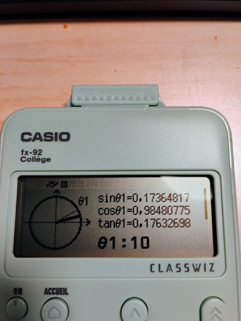
Cercle: Circle app (trigonometric circle,
semi-circle, hourly clock (Horloge))
|
The
fx-92 Collège is part of the Casio’s Classwiz series (think
fx-991CW and the international fx-82CW). The calculator has a back
button, four direction keys, an [ OK ] button, a button acts like a
scroll button. The home button (ACCUEIL) calls up the modes while
the configuration (CONFIG) shows the set up options.
The
calculator uses a comma as a fraction indicator instead of a decimal
point to align with how numbers are written in France.
In
France, the approximation of √92 is written as 9,591663047.
In
the United States, the approximation of √92 is written as
9.591663047.
Mathematical
Functions
Some
of the featured functions are:
Euclidean
division: |-. [ SECONDE ] [ ÷ ]. This function returns the
quotient and remainder.
Example:
2025 |- 47 returns Q = 43; R = 4
Last
Answer: [ Rép ]. This is the returns the last answer processed by
the previous calculation. This is often labeled elsewhere as Ans.
Fraction
Simplification: Simp. [ SECONDE ] [ Rèp ]. Simplifies fractions
and rational expressions or attempts to give a fraction
representation of a decimal.
Example:
.5757575757575757 >Simp returns 19/33.
Logarithm
and Natural Logarithm: These are not on the keyboard, but instead
found in the CATALOG – Analyse fonction menu.
Exponential
Function (e^x): The Euler constant (e ≈ 2,718281…) is found by
pressing [ CATALOG ], [ ↑ ], selecting Autre (Other) and selecting
e.
Catalog-Probabilitè:
%
Factorielle
(Factorial: n!)
Permutation
(nPr)
Combinasion
(Combinatio: nCr)
Nombre
alèatoire (Random Number, Ran#)
Entier
alèatoire (Random whole number, RandInt#(low; high))
Note
arguments are separated by a colon. (;)
Catalog-Calcul
numérique:
PGCD:
Greatest common divisor (GCD)
PPCM:
Least common multiple (LCM)
Valeur
absolue: Absolute value (abs, |x|)
Tronc.
À l’unité: Shown as Ent when called, this is the integer part
function.
Arrondi:
Rounds the number to the fix mode settings
Partie
entière: The greatest integer less than x.
Arrondi(;):
Rounds the number to any number of decimals.
Example:
Arond(π; 4) returns 3927 / 1250 = 3,1416
Catalog-Angl/Coord/Sexag…:
This
sub menu has angle designations (x°, x^r (radians), x^g (gradients),
polar/rectangular conversions, markers for
degrees/hours-minute-seconds calculations).
Catalog-Trigonométrique:
All
the trigonometric (sin, cos, tan) functions and their inverses.
These six functions are already on the keyboard.
Algorithmique
Mode: Algorithm
This
is the fx-92 Collège’s programming function. There is one program
space, which allows up to 900 bytes of memory. Each command takes
at least 4 bytes of memory. The language is similar to Scratch.
The
output screen is a split screen. On the top, a graph and drawing
screen. The dimensions of 191 pixel wide, 48 pixel height. The
graph dimensions are x = [-95,96] and y=[-24,24]. Draws can leave
the screen, up to ±999. At the bottom is one line where numerical
results and per-programmed messages are shown. Below is a table of
the commands that are available:
(Créer
un algorithme: Create an algorithm)
French
|
English
|
Function
|
Avancer de n
|
Move forward n
|
Move the point n points/pixels
|
Tourner de ⟲ Θ
|
Turn from ⟲ Θ
|
Rotate the arrow Θ degrees
|
S’ orienter à Θ
|
Orient yourself to Θ
|
Turn the pointer to angle Θ
|
Aller à x; y
|
Go to x; y
|
Move pointer to point (x,y)
|
Stylo écrit
|
Pen writes
|
Put the pen down to write
|
Stylo relevè
|
Pen raised
|
Raises the pen to stop writing
|
Metire var á
(Shown as expression → var)
|
Set var to
(Shown as expression → var)
|
Makes a calculation and sets it to a variable A – F, or z.
|
Demander valeur
(Shown as ? → var)
|
Ask for a value
(Shown as ? → var)
|
Prompts for a value to be stored in A – F, or z
|
Commenataire
(shown as one of four comments)
|
Comment out of four per-programmed strings
|
“Oui” Yes
“Non” No
“Nombre?” Number?
“Résultat :” Result :
Pauses execution
|
Afficher résult var
|
Show result var
|
Shows the contents of a variable and pauses execution
|
Style
|
Style (Style of Cursor)
|
Fléche: Arrow
Croix: Cross
|
Attendre
|
Pause
|
Pause execution of script
|
Répéter n ( ↑ )
|
Repeat n ( ↑ )
|
Repeat loop, n time (up to 10,000 times). Loop ends at ↑.
|
Répéter jusqúa cond
|
Repeat until cond
|
Repeat a loop until condition cond is met. =, ≠, >, <, ≥,
≤ are present in the CATALOG-ALGO menu
|
Si Alors (Fin)
|
If Then (End)
|
If-Then structure. =, ≠, >, <, ≥, ≤ are present in
the CATALOG-ALGO menu
|
Si Alors Sinon (Fin)
|
If Then Else (End)
|
If-Then-Else structure. =, ≠, >, <, ≥, ≤ are present
in the CATALOG-ALGO menu
|
Algorithms
start with the pointer at (0, 0) and the pen up. The pointer first
starts at angle Θ = 0° (right along the x-axis).
The
angle Θ is only accessed in this mode, [CATALOG], Algo, Θ (and only
in certain prompts).
The
variables x and y refer to the pixel coordinates. They cannot be
stored or asked for in this mode.
With
each command, you get a prompt screen to fill in the inputs.
When
the script pauses, press [ OK ] to continue.
Also
with OUTILS (options):
French
|
English
|
|
Copier & Insérer
|
Copy & Insert (at Paste)
|
Press [ OK ] to insert the line.
|
Insérer linger
|
Insert Row
|
Press [ OK ] to insert the line.
|
Tout supprimer
|
Delete the Script
|
To delete a line, press [ ←x ] instead.
|
The
fx-92 Collège is the second Casio calculator to have this type of
algorithm mode. It succeeds the fx-92+ Spèicale Collège.
Next
Sunday, February 16, we will explore the differences between the
fx-92 Collège’s algorithm program and the Turtle module in Python.
Final
Thoughts
The algorithm is erased when the calculator is turned off. I wish
this wasn’t the case but I can see why the calculator does not
retain programs. The fx-92 Collège is designed for teaching basic
coding. This is the reason I would like to see this model available
readily worldwide, as I think it would sell well. Even though the
target audience are middle school students, I think this calculator
can be enjoyed by everyone, at any age.
My only gripe: why aren’t the logarithm (log, ln) and exponential
(e^x) functions on the keyboard? I get that middle school students
probably don’t work with these functions, but the fx-92 Collège is
a scientific calculation, and it is customary to have these functions
on the keyboard. Not a deal breaker in any stretch of the
imagination, just a minor thing for me. I’m glad they are there.
If
you get a chance to get this calculator at a reasonable price, buy it.
Now I can hope that the AAA battery is used is a
universal AAA battery, I probably will have to invest in metric small
screwdrivers when it comes time to replace the battery.
Eddie
All
original content copyright, © 2011-2025. Edward Shore.
Unauthorized use and/or unauthorized distribution for commercial
purposes without express and written permission from the author is
strictly prohibited. This blog entry may be distributed for
noncommercial purposes, provided that full credit is given to the
author.